
Few new devices now include VGA connectors, and it generally coexists with DVI or the newer and more compact HDMI and DisplayPort interface connectors.
Design
VGA connectors and cables carry analog component RGBHV (red, green, blue, horizontal sync, vertical sync) video signals, and VESA Display Data Channel (VESA DDC) data.
The original IBM PS/2 defined different signals assignments. The IBM 8513 monitor defined pin 5 as "Self Test", which displays a white screen when the cable is disconnected (the pin is not connected to ground). The IBM PS/55 Display Adapter defined pin 9 as "+12V". It turns on the specific monitor when the system unit is powered on. In the PS/2, pin 9 was keyed by plugging the female connector hole; this prevented non-VGA 15 pin cables from being plugged into a VGA socket. Four pins carried Monitor ID bits, which were rarely used; VESA DDC redefined some of these pins and replaced the key pin with +5 V DC power supply. Devices that comply with the DDC host system standard provide 5 V ± 5% and supply a minimum of 50 mA to a maximum of 1 A.
The VGA interface is not engineered to be hot-swappable (i.e. the user cannot connect or disconnect the output device while the host is running), although in practice this can be done and usually does not cause damage to the hardware or other problems. However, nothing in the design ensures that the ground pins from the first make or the last break in the connection, so hot-swapping may introduce surges in signal lines that may or may not be adequately protected against damage. Also, depending on the hardware and software, monitor detection is sometimes unreliable when hot-plugging a VGA connection.
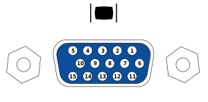
| Pin 1 | RED | Red video | |
|---|---|---|---|
| Pin 2 | GREEN | Green video | |
| Pin 3 | BLUE | Blue video | |
| Pin 4 | ID2/RES | Reserved since E-DDC, formerly monitor id. bit 2 | |
| Pin 5 | GND | Ground (HSync) | |
| Pin 6 | RED_RTN | Red return | |
| Pin 7 | GREEN_RTN | Green return | |
| Pin 8 | BLUE_RTN | Blue return | |
| Pin 9 | KEY/PWR | +5 V DC (powers EDID EEPROM chip on some monitors), formerly key | |
| Pin 10 | GND | Ground (VSync, DDC) | |
| Pin 11 | ID0/RES | Reserved since E-DDC, formerly monitor id. bit 0 | |
| Pin 12 | ID1/SDA | I²C data since DDC2, formerly monitor id. bit 1 | |
| Pin 13 | HSync | Horizontal sync | |
| Pin 14 | VSync | Vertical sync | |
| Pin 15 | ID3/SCL | I²C clock since DDC2 formerly monitors id. bit 3 | |
| The image and table detail the 15-pin VESA DDC2/E-DDC connector; the diagram’s pin numbering is that of a female connector functioning as the graphics adapter output. In the male connector, this pin numbering corresponds with the cable’s wire-and-solder side. | |||


0 Comments